Norbert Doerry, Mohammed M Islam, John Prousalidis
Design of Shipboard Power System Grounding / Earthing
Norbert Doerry, Mohammed M Islam, John Prousalidis
Design of Shipboard Power System Grounding / Earthing
- Gebundenes Buch
- Merkliste
- Auf die Merkliste
- Bewerten Bewerten
- Teilen
- Produkt teilen
- Produkterinnerung
- Produkterinnerung
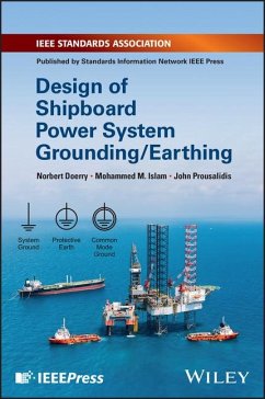
This book delves into the diverse prerequisites for grounding and earthing in contemporary ship power systems, addressing the evolving landscape of ship design influenced by power electronics The introduction of transformative technologies such as variable frequency drives and electric propulsion systems has heightened the complexity of shipboard grounding systems. This complexity necessitates accommodation for robust electronic systems, extending the focus beyond traditional grounding aspects to include common mode grounding and its profound design implications. Engineers now require a…mehr
Andere Kunden interessierten sich auch für
![McGraw-Hill's NEC 2014 Grounding and Earthing Handbook McGraw-Hill's NEC 2014 Grounding and Earthing Handbook]() David StockinMcGraw-Hill's NEC 2014 Grounding and Earthing Handbook72,99 €
David StockinMcGraw-Hill's NEC 2014 Grounding and Earthing Handbook72,99 €![Optimum Design of Grounding System of High Voltage Substations Optimum Design of Grounding System of High Voltage Substations]() Ossama GoudaOptimum Design of Grounding System of High Voltage Substations46,99 €
Ossama GoudaOptimum Design of Grounding System of High Voltage Substations46,99 €![Electrical Installations Shipboard Electrical Installations Shipboard]() Mohammed M IslamElectrical Installations Shipboard141,99 €
Mohammed M IslamElectrical Installations Shipboard141,99 €![Understanding Symmetrical Components for Power System Modeling Understanding Symmetrical Components for Power System Modeling]() J C DasUnderstanding Symmetrical Components for Power System Modeling107,99 €
J C DasUnderstanding Symmetrical Components for Power System Modeling107,99 €![Grounding and Shielding in Facilities Grounding and Shielding in Facilities]() Ralph MorrisonGrounding and Shielding in Facilities277,99 €
Ralph MorrisonGrounding and Shielding in Facilities277,99 €![Power Systems Grounding Power Systems Grounding]() Md. Abdus SalamPower Systems Grounding77,99 €
Md. Abdus SalamPower Systems Grounding77,99 €![Power Systems Grounding Power Systems Grounding]() Md. Abdus SalamPower Systems Grounding70,99 €
Md. Abdus SalamPower Systems Grounding70,99 €-
-
-
This book delves into the diverse prerequisites for grounding and earthing in contemporary ship power systems, addressing the evolving landscape of ship design influenced by power electronics The introduction of transformative technologies such as variable frequency drives and electric propulsion systems has heightened the complexity of shipboard grounding systems. This complexity necessitates accommodation for robust electronic systems, extending the focus beyond traditional grounding aspects to include common mode grounding and its profound design implications. Engineers now require a comprehensive guide to navigate the intricacies of shipboard electric power systems. To meet this imperative, Design of Shipboard Power System Grounding/Earthing provides an in-depth exploration of the subject. It offers a step-by-step initiation into the grounding process, supported by numerous case studies for enhanced comprehension. Aligned with both US and international standards, this book serves as an essential resource for engineers engaged in the design and implementation of shipboard power systems. Key highlights for readers encompass meticulous comparisons between terrestrial power system grounding and shipboard power grounding, as well as comprehensive discussions on high resistance grounding, shipboard AC system grounding requirements, DC system grounding, and more, including common mode grounding and earthing. The inclusion of abundant engineering drawings supports significant case studies, enhancing the practical application of the material. Designed to cater to a broad audience, Design of Shipboard Power System Grounding/Earthing is invaluable for readers involved with shipboard electrical systems, including shipbuilders, ship designers, ship operators, and those in regulatory bodies such as the Navy, USCG, ABS, among others. This resource is also well-suited for academicians, particularly final-year undergraduate and graduate students in marine electrical engineering programs.
Hinweis: Dieser Artikel kann nur an eine deutsche Lieferadresse ausgeliefert werden.
Hinweis: Dieser Artikel kann nur an eine deutsche Lieferadresse ausgeliefert werden.
Produktdetails
- Produktdetails
- Verlag: Wiley
- Seitenzahl: 368
- Erscheinungstermin: 15. Januar 2025
- Englisch
- Abmessung: 229mm x 152mm x 21mm
- Gewicht: 658g
- ISBN-13: 9781119933083
- ISBN-10: 1119933080
- Artikelnr.: 70948800
- Herstellerkennzeichnung
- Libri GmbH
- Europaallee 1
- 36244 Bad Hersfeld
- gpsr@libri.de
- Verlag: Wiley
- Seitenzahl: 368
- Erscheinungstermin: 15. Januar 2025
- Englisch
- Abmessung: 229mm x 152mm x 21mm
- Gewicht: 658g
- ISBN-13: 9781119933083
- ISBN-10: 1119933080
- Artikelnr.: 70948800
- Herstellerkennzeichnung
- Libri GmbH
- Europaallee 1
- 36244 Bad Hersfeld
- gpsr@libri.de
Norbert Doerry, PhD, is a naval engineer with a PhD in naval electrical power systems and with over 35 years of experience in innovation, invention, science and technology, research and development acquisition, design, construction, in-service support, and ship operations. Mohammed M. Islam currently serves as the Chair of IEEE 45.7 Switchboard Standard working group. He has been involved in the "All Electric Ship Design and Development" and R&D programs for many years. He was the principal investigator of the Ship Smart-System Design (S3D) feasibility study, an ONR funded resaerch and development project. He was the R&D manager of Ship System Applied Science at Northrop Grumman Ship Systems. He served as the IEEE-45 central committee chair and chair of numerous IEEE 45 series Standards. John Prousalidis, PhD, is a Professor with the Academic Staff of the School of naval Architecture and Marine Engineering. He is a reviewer of IEEE and IET journal papers, a member of the Editorial Board of the IET journal Power Systems in Transportation, and of the International Journal of Ocean Systems Management (IJOSM) of Indersience Publishers.
About the Authors xiii
Preface xv
1 Introduction 1
1.1 General 1
1.2 Grounding and Earthing Definitions 2
1.3 Common Mode Terminology 4
1.4 Types of Power Distribution Systems 5
1.5 Types of Power System Grounding Systems 7
1.6 Modeling and Simulation 8
1.7 Book Overview 9
1.8 Legal Notice 13
References 13
2 System Grounding: Shipboard Ungrounded AC Systems (No Greater than 1 kV)
15
2.1 Characteristics 15
2.2 Modeling Shipboard Ungrounded AC Low-Voltage Distribution Systems 19
2.2.1 Low-Voltage AC Cable Model 20
2.2.2 Bus Duct 25
2.2.3 EMI Filters 25
2.2.4 Generators and Motors 25
2.2.5 Transformers 26
2.2.6 System Simulation 26
2.3 Ground Fault Detection 29
2.4 Ground Fault Localization 37
2.5 Electrical Insulation Impacts 41
2.6 One-Line Diagram Symbology 41
2.7 Case Studies 42
2.7.1 Modeling a Low-Voltage AC Cable 42
2.7.2 Modeling a Cable Line-to-Line Capacitance for GFCI Calculations 44
2.8 Reference Cable Data 49
References 53
3 System Grounding: Shipboard HRG AC Low-Voltage Distribution Systems (No
Greater than 1 kV) 55
3.1 Characteristics 55
3.2 Grounding Circuit 64
3.2.1 Grounding Resistor Characteristics 64
3.2.2 Neutral Ground 66
3.2.3 Zigzag Transformer 66
3.2.4 Wye-Delta Transformer 67
3.2.5 Wye-Broken Delta Transformer 68
3.2.6 One-Line Diagram Symbology 69
3.2.7 Grounding Transformer Characteristics 70
3.2.8 Grounding Transformer Saturation 70
3.3 Location of Grounding Circuit 74
3.4 Ground Fault Detection 78
3.5 Ground Fault Localization 79
3.5.1 Pulsing System 79
3.5.2 Low-Resistance Ground Fault Clearing 80
3.5.3 Common Mode Current Phase Measurements 82
3.6 Electrical Insulation Impacts 83
3.7 Limiting Ground Fault Current 83
References 84
4 System Grounding: Shipboard Solidly Grounded AC Systems (No Greater than
400 V) 85
4.1 Characteristics 85
4.2 Design Considerations 89
4.2.1 General 89
4.2.2 Transformers 89
4.2.3 Sub-power Panels 94
4.2.4 Ground Fault Protection 94
4.3 Cable Insulation Colors 97
5 System Grounding: Shipboard HRG AC Primary Distribution Systems (Greater
than 1 kV) 99
5.1 Characteristics 99
5.2 Grounding Circuit 100
5.2.1 Grounding Resistor Transformer 100
5.2.2 Wye-Broken Delta Transformer 101
5.2.3 Grounding Resistor Design 102
5.3 Modeling Shipboard HRG AC Primary Distribution Systems 102
5.3.1 Three-Conductor Shielded Cable Models 102
5.3.2 Single-Conductor Cable and Insulated Bus Pipe Models 107
5.3.3 EMI and Harmonic Filters 109
5.3.4 Generators and Motors 109
5.3.5 Transformers 112
5.3.6 System Simulation 114
5.4 Location of Grounding Circuit 117
5.5 Ground Fault Detection 118
5.6 Ground Fault Localization 118
5.7 Electrical Insulation Impact 119
5.7.1 Insulation Voltage Rating 119
5.7.2 Partial Discharge 119
5.8 Limiting Ground Fault Current 120
5.9 Cable Terminations 120
References 122
6 System Grounding: Shipboard Ungrounded DC Systems (No Greater than 1 kV)
125
6.1 Characteristics 125
6.2 Modeling 128
6.2.1 Two-Conductor Unshielded Cable 128
6.2.2 Four-Conductor Unshielded Cable 131
6.2.3 Passive Rectifiers 133
6.2.4 Active Rectifiers 133
6.3 Ground Fault Detection 133
6.4 Ground Fault Localization 136
6.5 Auctioneering Diodes 140
6.6 Electrical Insulation Impacts 143
6.7 Cable Insulation Colors 143
References 143
7 System Grounding: Shipboard HRG DC Systems 145
7.1 Characteristics 145
7.2 Grounding Methods 146
7.2.1 Line-to-Ground Resistors 146
7.2.2 Split Power Supply 149
7.2.3 Grounding Bus 150
7.2.4 Current Sensors 150
7.3 Modeling 151
7.3.1 Four-Conductor Shielded Cable 151
7.4 Ground Fault Detection 154
7.5 Ground Fault Localization 154
7.6 Electrical Insulation Impacts 158
7.6.1 Insulation Voltage Rating 158
7.6.2 Partial Discharge 158
7.6.3 Space Charge 159
References 159
8 System Grounding: Shipboard Solidly Grounded DC Systems (No Greater than
1 kV) 161
8.1 Characteristics 161
8.2 Corrosion 163
8.3 Modeling Shipboard Solidly Grounded DC Systems 163
8.4 Ground Fault Detection and Localization 164
8.5 Electrical Insulation Impacts 166
8.6 Cable Insulation Colors 166
9 Designing Shipboard Power System Grounding/Earthing Systems 167
9.1 Introduction 167
9.2 AC Primary Distribution Systems 168
9.3 AC Low-Voltage Distribution Systems 170
9.4 AC Low-Voltage Secondary Distribution Systems 171
9.5 AC Low-Voltage Special Circuits 172
9.6 dc Primary Distribution Systems 172
9.7 dc Low-Voltage Distribution Systems 173
9.8 dc Low-Voltage Secondary Distribution Systems 173
9.9 dc Low-Voltage Special Circuits 174
9.10 Examples 174
9.10.1 AC Low-Voltage Distribution System for Commercial Mechanical Drive
Ship 174
9.10.2 AC Primary Distribution System for Commercial Integrated Power
System Ship 180
9.10.3 Low-Voltage AC Zonal Distribution 185
9.10.4 Zonal AC Primary Distribution 185
9.10.5 Commercial Ship DC Distribution 190
9.10.6 Zonal DC Primary Distribution 192
References 193
10 Power Conversion Equipment Grounding 195
10.1 Introduction 195
10.2 Transformers 195
10.3 Isolated Power Conversion Equipment 198
10.4 Non-Isolated Power Conversion Equipment 199
10.5 cm Voltage and Current Control 201
10.6 VFD Cable 202
10.6.1 VFD Cable Description and Use 202
10.6.2 VFD Cable Modeling (Without Conductor Shields) 205
10.6.3 VFD Cable Modeling (with Conductor Shields) 208
10.7 Examples 209
10.7.1 Directly Connected VFD and Motor - No More than 1 kV 209
10.7.2 Transformer-Supplied VFD and Motor - No Greater than 1 kV 212
10.7.3 Propulsion Motor Drives - Greater than 1 kV 214
10.8 Maintenance Considerations 217
References 219
11 Shore Power (Cold Ironing) Connection Grounding 221
11.1 Introduction 221
11.2 Low-Voltage Shore Connections 223
11.3 High-Voltage Shore Connections 227
References 237
12 Vehicle Connections Grounding 239
12.1 Introduction 239
12.2 Design Considerations 239
12.2.1 Aircraft Static Electricity 239
12.2.2 Vehicle Electrical Systems 241
References 242
13 Common Mode Grounding: Impact of Common Mode Currents and Voltages on
Grounding Systems 243
13.1 Common Mode Fundamentals 243
13.2 Relationship of CM to EMI and EMC 256
13.3 Control of CM Currents and Voltages 257
13.3.1 Equipment Design 258
13.3.2 Cable Shields, Drain Wires, and Ground Conductors 258
13.3.3 Inductors and CM Chokes 261
13.3.4 Capacitors and CM Shunts 264
13.3.5 cm Control Philosophies 267
13.3.5.1 Cable Only Solution 267
13.3.5.2 Cable and CM Choke Solution 268
13.3.5.3 Controlling CM at the Interfaces 268
13.3.5.4 Controlling CM at the HRG 270
13.3.5.5 Controlling CM Within Motors and Generators 270
13.3.6 cm AC Limits 271
13.3.7 cm dc Limits 273
13.4 Advanced CM Modeling 275
13.5 Design Considerations 276
References 276
14 Protective Earthing: Bonding 279
14.1 Introduction 279
14.2 Design Considerations 280
14.3 Testing 286
References 286
15 Current-Related Corrosion 289
15.1 Introduction 289
15.2 Galvanic Corrosion Theory 289
15.3 Impact of Current on Galvanic Corrosion 296
15.3.1 dc Current 296
15.3.2 AC Current 297
15.4 Shipboard Corrosion 297
15.4.1 Hull and Structure Corrosion 297
15.4.2 Propulsion Shaft Corrosion 298
15.4.3 Electrical Connection Corrosion 299
15.4.4 Bearing Corrosion 299
15.5 Cathodic Protection Systems 300
15.5.1 Sacrificial Anodes 300
15.5.2 Impressed Current Cathodic Protection 302
References 303
16 Lightning Protection Systems 305
16.1 Introduction 305
16.2 Design Considerations 308
16.2.1 Zone of Protection 308
16.2.2 Air Terminals 310
16.2.3 Down Conductors 311
16.2.4 Low-Impedance Ground Connection 312
16.2.5 Surge Protection 312
References 314
17 Grounding Systems for Nonmetallic Hull Ships 317
17.1 Design Considerations 317
Reference 319
Appendix A Glossary 321
Appendix B Acronyms and Abbreviations 337
Appendix C Impact of Electric Current on Humans 339
Index 345

