Hirofumi Akagi
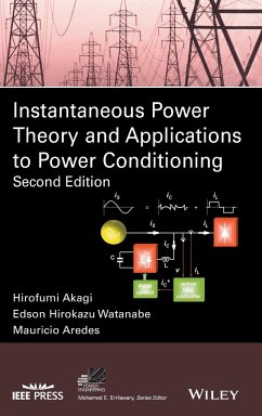
Instantaneous Power Theory and Applications to Power Conditioning
Hirofumi Akagi
Instantaneous Power Theory and Applications to Power Conditioning
- Gebundenes Buch
- Merkliste
- Auf die Merkliste
- Bewerten Bewerten
- Teilen
- Produkt teilen
- Produkterinnerung
- Produkterinnerung
This book covers instantaneous power theory as well as the importance of design of shunt, series, and combined shunt-series power active filters and hybrid passive-active power filters * Illustrates pioneering applications of the p-q theory to power conditioning, which highlights distinct differences from conventional theories * Explores p-q-r theory to give a new method of analyzing the different powers in a three-phase circuit * Provides exercises at the end of many chapters that are unique to the second edition
Andere Kunden interessierten sich auch für
![Power Conversion and Control of Wind Energy Systems Power Conversion and Control of Wind Energy Systems]() Bin WuPower Conversion and Control of Wind Energy Systems121,99 €
Bin WuPower Conversion and Control of Wind Energy Systems121,99 €![Power Generation, Operation and Control Power Generation, Operation and Control]() Allen J. WoodPower Generation, Operation and Control135,99 €
Allen J. WoodPower Generation, Operation and Control135,99 €![Rating of Electric Power Cables in Unfavorable Thermal Environment Rating of Electric Power Cables in Unfavorable Thermal Environment]() George J. AndersRating of Electric Power Cables in Unfavorable Thermal Environment166,99 €
George J. AndersRating of Electric Power Cables in Unfavorable Thermal Environment166,99 €![Handbook of Power Quality Handbook of Power Quality]() Angelo BagginiHandbook of Power Quality167,99 €
Angelo BagginiHandbook of Power Quality167,99 €![Flexible Power Transmission Flexible Power Transmission]() Jos ArrillagaFlexible Power Transmission122,99 €
Jos ArrillagaFlexible Power Transmission122,99 €![Power System Monitoring and Control Power System Monitoring and Control]() Hassan BevraniPower System Monitoring and Control109,99 €
Hassan BevraniPower System Monitoring and Control109,99 €![The Principles of Electronic and Electromechanic Power Conversion The Principles of Electronic and Electromechanic Power Conversion]() Braham FerreiraThe Principles of Electronic and Electromechanic Power Conversion97,99 €
Braham FerreiraThe Principles of Electronic and Electromechanic Power Conversion97,99 €-
-
-
This book covers instantaneous power theory as well as the importance of design of shunt, series, and combined shunt-series power active filters and hybrid passive-active power filters * Illustrates pioneering applications of the p-q theory to power conditioning, which highlights distinct differences from conventional theories * Explores p-q-r theory to give a new method of analyzing the different powers in a three-phase circuit * Provides exercises at the end of many chapters that are unique to the second edition
Hinweis: Dieser Artikel kann nur an eine deutsche Lieferadresse ausgeliefert werden.
Hinweis: Dieser Artikel kann nur an eine deutsche Lieferadresse ausgeliefert werden.
Produktdetails
- Produktdetails
- Verlag: John Wiley & Sons / Wiley-IEEE Press
- Seitenzahl: 470
- Erscheinungstermin: 24. Februar 2017
- Englisch
- Abmessung: 240mm x 161mm x 30mm
- Gewicht: 868g
- ISBN-13: 9781118362105
- ISBN-10: 1118362101
- Artikelnr.: 38106161
- Herstellerkennzeichnung
- Wiley John + Sons
- Southern Gate, Chichester
- P019 8SQ West Sussex, GB
- 0130 815199
Hirofumi Akagi is a Professor in the department of electrical and electronic engineering at the Tokyo Institute of Technology. His research interest includes power conversion systems and its applications to industry, transportation, and utility. He has authored and coauthored some 120 IEEE Transactions papers and two invited papers published in Proceedings of the IEEE in 2001 and 2005. He was elected as an IEEE Fellow in 1996, a Distinguished Lecturer of the IEEE Power Electronics and Industry Applications Societies for 1998-1999. He received six IEEE Transactions prize paper awards, and 15 IEEE Industry Applications Society Committee prize paper awards. He is the recipient of the 2001 IEEE Power Electronics William E. Newell Award, the 2004 IEEE Industry Applications Society Outstanding Achievement Award, the 2008 IEEE Richard H. Kaufmann Technical Field Award, and the 2012 IEEE Power & Energy Society Nari Hingorani Custom Power Award. Dr. Akagi served as the President of the IEEE Power Electronics Society for 2007-2008. Since January 2015, he has been serving as the IEEE Division II Director. Edson Hirokazu Watanabe is a Professor at COPPE/Federal University of Rio de Janeiro, where he teaches Power Electronics. His main fields of interests are converters analysis, modeling and design, active filters and FACTS technologies. Dr. Watanabe has more than 50 journal papers and more than 200 conference papers. He is a member of the IEE-Japan, The Brazilian Society for Automatic Control, The Brazilian Power Electronics Society, CIGRE and Power Engineering, Industry Applications and Power Electronics Societies of IEEE. In 2005, he was admitted to the National Order of Scientific Merit, Brazil. In 2013, he received the IEEE Power & Energy Society Nari Hingorani FACTS Award and became member of the National (Brazil) Academy of Engineering and in 2015 he was elected a member of the Brazilian Academy of Sciences. Mauricio Aredes received the B.Sc. degree from UFF - Fluminense Federal University, Rio de Janeiro State in 1984, the M.Sc. degree in Electrical Engineering from UFRJ - Federal University of Rio de Janeiro in 1991, and the Dr.-Ing. degree (summa cum laude) from Technische Universität Berlin in 1996. In 1997, he became an Associate Professor at the Federal University of Rio de Janeiro, where he teaches Power Electronics. His main research area includes HVDC and FACTS systems, active filters, Custom Power, Renewable Energy Systems, and Power Quality Issues.
PREFACE xiii CHAPTER 1 INTRODUCTION 1 1.1 Concepts and Evolution of
Electric Power Theory 1 1.2 Applications of the P-q Theory to Power
Electronics Equipment 4 1.3 Harmonic Voltages in Power Systems 5 1.4
Identified and Unidentified Harmonic-Producing Loads 6 1.5 Harmonic Current
and Voltage Sources 8 1.6 Basic Principles of Harmonic Compensation 9 1.7
Basic Principle of Power Flow Control 13 References 15 CHAPTER 2 ELECTRIC
POWER DEFINITIONS: BACKGROUND 17 2.1 Power Definitions Under Sinusoidal
Conditions 18 2.2 Voltage and Current Phasors and Complex Impedance 20 2.3
Complex Power and Power Factor 21 2.4 Concepts of Power Under Nonsinusoidal
Conditions: Conventional Approaches 22 2.4.1 Power Definitions by Budeanu
22 2.4.1.A Power Tetrahedron and Distortion Factor 25 2.4.2 Power
Definitions by Fryze 27 2.5 Electric Power in Three-Phase Systems 28 2.5.1
Classifications of Three-Phase Systems 28 2.5.2 Power in Balanced
Three-Phase Systems 31 2.5.3 Power in Three-Phase Unbalanced Systems 33 2.6
Summary 34 2.7 Exercises 34 References 35 CHAPTER 3 THE INSTANTANEOUS POWER
THEORY 37 3.1 Basis of the p-q Theory 37 3.1.1 Historical Background of the
p-q Theory 38 3.1.2 The Clarke Transformation 39 3.1.2.A Calculation of
Voltage and Current Vectors When Zero-Sequence Components Are Excluded 41
3.1.3 Three-Phase Instantaneous Active Power in Terms of Clarke Components
43 3.1.4 The Instantaneous Powers of the p-q Theory 44 3.2 The p-q Theory
in Three-Phase, Three-Wire Systems 44 3.2.1 Comparisons with the
Conventional Theory 48 3.2.1.A Example #1--Sinusoidal Voltages and Currents
49 3.2.1.B Example #2--Balanced Voltages and Capacitive Loads 49 3.2.1.C
Example #3--Sinusoidal Balanced Voltage and Nonlinear Load 50 3.2.2 Use of
the p-q Theory for Shunt Current Compensation 54 3.2.2.A Examples of
Appearance of Hidden Currents 59 3.2.3 The Dual p-q Theory 63 3.3 The p-q
Theory in Three-Phase, Four-Wire Systems 65 3.3.1 The Zero-Sequence Power
in a Three-Phase Sinusoidal Voltage Source 67 3.3.2 Presence of
Negative-Sequence Components 68 3.3.3 General Case Including Distortions
and Imbalances in the Voltages and in the Currents 69 3.3.4 Physical
Meanings of the Instantaneous Real, Imaginary, and Zero-Sequence Powers 74
3.3.5 Avoiding the Clarke Transformation in the p-q Theory 75 3.3.6
Modified p-q Theory 77 3.4 Instantaneous abc Theory 81 3.4.1 Active and
Nonactive Current Calculation by Means of a Minimization Method 83 3.4.2
Generalized Fryze Currents Minimization Method 88 3.5 Comparisons Between
the p-q Theory and the abc Theory 91 3.5.1 Selection of Power Components to
be Compensated 95 3.6 The p-q-r Theory 97 3.7 Summary 104 3.8 Exercises 105
References 106 CHAPTER 4 SHUNT ACTIVE FILTERS 111 4.1 General Description
of Shunt Active Filters 113 4.1.1 PWM Converters for Shunt Active Filters
114 4.1.2 Active Filter Controllers 115 4.2 Three-Phase, Three-Wire Shunt
Active Filters 118 4.2.1 Active Filters for Constant Power Compensation 119
4.2.2 Active Filters for Sinusoidal Current Control 135 4.2.2.A
Positive-Sequence Voltage Detector 138 4.2.2.B Simulation Results 145 4.2.3
Active Filters for Current Minimization 145 4.2.4 Active Filters for
Harmonic Damping 149 4.2.4.A Shunt Active Filter Based on Voltage Detection
151 4.2.4.B Active Filter Controller Based on Voltage Detection 152 4.2.4.C
An Application Case of an Active Filter for Harmonic Damping 156 4.2.5 A
Digital Controller 171 4.2.5.A System Configuration of the Digital
Controller 172 4.2.5.B Current Control Methods 177 4.3 Three-Phase,
Four-Wire Shunt Active Filters 180 4.3.1 Converter Topologies for
Three-Phase, Four-Wire Systems 181 4.3.2 Dynamic Hysteresis-Band Current
Controller 182 4.3.3 Active Filter dc Voltage Regulator 184 4.3.4 Optimal
Power Flow Conditions 185 4.3.5 Constant Instantaneous Power Control
Strategy 187 4.3.6 Sinusoidal Current Control Strategy 189 4.3.7
Performance Analysis and Parameter Optimization 192 4.3.7.A Influence of
the System Parameters 192 4.3.7.B Dynamic Response of the Shunt Active
Filter 193 4.3.7.C Economical Aspects 198 4.3.7.D Experimental Results 199
4.4 Compensation Methods Based on the p-q-r Theory 204 4.4.1 Reference
Power Control Method 206 4.4.2 Reference Current Control Method 211 4.4.3
Alternative Control Method 213 4.4.4 The Simplified Sinusoidal Source
Current Strategy 215 4.4.4.A The PLL Circuit and the Positive-Sequence
Detector 215 4.4.4.B The Sinusoidal Source Current Control Strategy with
Energy Balance Inside the Active Filter 217 4.5 Comparisons Between Control
Methods Based on the p-q Theory and the p-q-r Theory 218 4.6 Shunt
Selective Harmonic Compensation 224 4.7 Summary 231 4.8 Exercises 231
References 233 CHAPTER 5 HYBRID AND SERIES ACTIVE FILTERS 237 5.1 Basic
Series Active Filter 237 5.2 Combined Series Active Filter and Shunt
Passive Filter 239 5.2.1 Example of an Experimental System 242 5.2.1.A
Compensation Principle 243 5.2.1.B Filtering Characteristics 245 5.2.1.C
Control Circuit 246 5.2.1.D Filter to Suppress Switching Ripples 248
5.2.1.E Experimental Results 249 5.2.2 Some Remarks about the Hybrid
Filters 252 5.3 Series Active Filter Integrated with a Double-Series Diode
Rectifier 253 5.3.1 The First-Generation Control Circuit 255 5.3.1.A
Circuit Configuration and Delay Time 255 5.3.1.B Stability of the Active
Filter 257 5.3.2 The Second-Generation Control Circuit 258 5.3.3 Stability
Analysis and Characteristics Comparison 260 5.3.3.A Transfer Function of
the Control Circuits 260 5.3.3.B Characteristics Comparisons 261 5.3.4
Design of a Switching-Ripple Filter 263 5.3.4.A Design Principle 263
5.3.4.B Effect on the System Stability 263 5.3.4.C Experimental Testing 264
5.3.5 Experimental Results 266 5.4 Comparisons Between Hybrid and Pure
Active Filters 268 5.4.1 Low-Voltage Transformerless Hybrid Active Filter
268 5.4.2 Low-Voltage, Transformerless, Pure Shunt Active Filter 271 5.4.3
Comparisons through Simulation Results 273 5.5 Hybrid Active Filters for
Medium-Voltage Motor Drives 274 5.5.1 Hybrid Active Filter for a
Three-Phase Six-Pulse Diode Rectifier 275 5.5.1.A System Configuration 275
5.5.1.B Experimental System 277 5.5.1.C Control System 277 5.5.1.D Common
Sixth-Harmonic Zero-Sequence Voltage Injection 281 5.5.1.E Three-Phase
Second-Harmonic Negative Sequence Voltages Injection 283 5.5.1.F
Experimental Results 286 5.5.1.G Appendix 292 5.5.2 Hybrid Active Filter
for a Three-Phase 12-Pulse Diode Rectifier 292 5.5.2.A Medium-Voltage
High-Power Motor Drive Systems 293 5.5.2.B Experimental System 295 5.5.2.C
Control System 298 5.5.2.D Three-Phase Second-Harmonic Negative Sequence
Voltages Injection 300 5.5.2.E Experimental Results 303 5.5.2.F Overall
System Efficiency 308 5.6 Summary 308 5.7 Exercises 309 References 310
CHAPTER 6 COMBINED SERIES AND SHUNT POWER CONDITIONERS 313 6.1 The Unified
Power Flow Controller 314 6.1.1 FACTS and UPFC Principles 315 6.1.1.A
Voltage Regulation Principle 317 6.1.1.B Power Flow Control Principle 318
6.1.2 A Controller Design for the UPFC 321 6.1.3 UPFC Approach Using a
Shunt Multipulse Converter 328 6.1.3.A Six-Pulse Converter 328 6.1.3.B
Quasi 24-Pulse Converter 332 6.1.3.C Control of Active and Reactive Power
in Multipulse Converters 334 6.1.3.D Shunt Multipulse Converter Controller
336 6.2 The Unified Power Quality Conditioner 339 6.2.1 General Description
of the UPQC 340 6.2.2 A Three-Phase, Four-Wire UPQC 342 6.2.2.A Power
Circuit of the UPQC 343 6.2.2.B The UPQC Controller 344 6.2.2.C Analysis of
the UPQC Dynamic 353 6.2.3 The UPQC Combined with Passive Filters (the
Hybrid UPQC) 370 6.2.3.A Controller of the Hybrid UPQC 374 6.2.3.B
Experimental Results 380 6.3 The Universal Active Power Line Conditioner
386 6.3.1 General Description of the UPLC 386 6.3.2 The Controller of the
UPLC 389 6.3.2.A Controller for Configuration #2 of the UPLC 396 6.3.3
Performance of the UPLC 397 6.3.3.A Normalized System Parameters 397
6.3.3.B Simulation Results of Configuration #1 of the UPLC 401 6.3.3.C
Simulation Results of Configuration #2 of the UPLC 409 6.3.4 General
Aspects 411 6.4 Combined Shunt-Series Filters for AC and DC Sides of
Three-Phase Rectifiers 411 6.4.1 The Combined Shunt-Series Filter 414 6.4.2
Instantaneous Real and Imaginary Powers in the ac Source 415 6.4.3 The
Instantaneous Power in the dc Side of the Rectifier 416 6.4.4 Comparison of
Instantaneous Powers on the ac and dc Sides of the Rectifier 418 6.4.5
Control Algorithm of the Active Shunt-Series Filter 418 6.4.6 The Common dc
Link 421 6.4.7 Digital Simulation 424 6.4.8 Experimental Results 426 6.5
Summary 427 6.6 Exercises 428 References 429 INDEX 431

